|
Torna all'indice di Tecnica & Medicina
|
 |
|
|
Torna all'indice di Tecnica & Medicina
|
|
|
|
117. DIVING REGULATORS (from Wikipedia, the free encyclopedia) A diving regulator is a pressure regulator used in scuba or surface supplied diving equipment that reduces pressurized breathing gas to ambient pressure and delivers it to the diver. The gas may be air or one of a variety of specially blended breathing gases. The gas may be supplied from a cylinder worn by the diver (as in a scuba set) or via a hose from a compressor or a bank of cylinders on the surface (as in surface-supplied diving). A gas pressure regulator has one or more valves in series which reduce pressure from the source, and use the downstream pressure as feedback to control the delivered pressure, lowering the pressure at each stage. The terms "regulator" and "demand valve" are often used interchangeably, but a demand valve is the part of a regulator that delivers gas only while the diver is breathing in, and reduces the gas pressure to ambient. In single hose regulators, the demand valve is part of the second stage, which is held in the diver's mouth by a mouthpiece. In double hose regulators the demand valve is part of the regulator attached to the cylinder. TYPES OF FIRST STAGEThe mechanism inside the first stage can be of the diaphragm type or the piston type. Both types can be balanced or unbalanced. Unbalanced regulators have the cylinder pressure pushing the first stage upstream valve closed, which is opposed by the intermediate stage pressure and a spring. As cylinder pressure falls the closing force is less, so the regulated pressure increases at lower tank pressure. To keep this pressure rise within acceptable limits the high-pressure orifice size was limited, but this decreased the total flow capacity of the regulator. A balanced regulator keeps about the same ease of breathing at all depths and pressures, by using the cylinder pressure to also indirectly oppose the opening of the first stage valve.
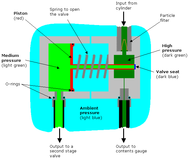
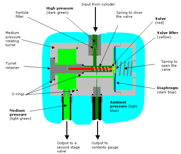
Piston type first stage Some components of piston-type first stages are easier to manufacturer and have a simpler design than the diaphragm type. They need more careful maintenance because some internal moving parts are exposed to water and any contaminants in the water. The piston in the first stage is rigid and acts directly on the seat of the valve. The pressure in the medium (aka intermediate) pressure chamber drops when the diver inhales from the second stage valve, this causes the piston to lift off the stationary valve seat as the piston slides into the intermediate pressure chamber. The now open valve permits high pressure gas to flow into the medium pressure chamber until the pressure in the chamber has risen enough to push the piston back into its original position against the seat and thus close the valve. Diaphragm type first stage Diaphragm-type first stages are more complex and have more components than the piston type. Their design makes them particularly suited to cold water diving and to working in saltwater and water containing a high degree of suspended particles, silt, or other contaminating materials, since the only parts exposed to the water are the valve opening spring and the diaphragm, all other parts are sealed off from the environment. In some cases the diaphragm and spring are also sealed from the environment. The diaphragm is a flexible cover to the medium (intermediate) pressure chamber. When the diver consumes gas from the second stage, the pressure falls in the medium pressure chamber and the diaphragm deforms inwards pushing against the valve lifter. This opens the high pressure valve permitting gas to flow past the valve seat into the medium-pressure chamber. When the diver stops inhaling, pressure in the medium pressure chambers rises and the diaphragm returns to its neutral flat position and no longer presses on the valve lifter shutting off the flow until the next breath is taken.
Most cylinder valves are currently of the K-valve type, which is a simple manually operated screw-down on-off valve. In the mid-1960s, J-valves were widespread. J-valves contain a spring-operated valve that is restricts or shuts off flow when tank pressure falls to 300-500 psi, causing breathing resistance and warning the diver that he or she is dangerously low on air. The reserve air is released by pulling a reserve lever on the valve. J-valves fell out of favor with the introduction of pressure gauges, which allow divers to keep track of their air underwater, especially as the valve-type is vulnerable to accidental release of reserve air and increases the cost and servicing of the valve. J-valves are occasionally still used when work is done in visibility so poor that the pressure gauge cannot be seen, even with a light. Risk of the regulator becoming blocked with ice As gas leaves the cylinder it decreases in pressure in the first stage, becoming very cold due to adiabatic expansion. Where the ambient water temperature is less than 5°C any water in contact with the regulator may freeze. If this ice jams the diaphragm or piston spring, preventing the valve closing, a free-flow may ensue that can empty a full cylinder within a minute or two, and the free-flow causes further cooling in a positive feedback loop. Generally the water that freezes is in the ambient pressure chamber around a spring that keeps the valve open and not moisture in the breathing gas from the cylinder, but that is also possible if the air is not adequately filtered. The modern trend of using more plastics, instead of metals, in regulators encourages freezing because it insulates the inside of a cold regulator from the warmer surrounding water. Cold water kits can be used to reduce the risk of freezing inside the regulator. Some regulators come with this as standard, and some others can be retrofitted. Environmental sealing of the diaphragm main spring chamber using a soft secondary diaphragm and hydrostatic transmitter or a silicone, alcohol or glycol/water mixture antifreeze liquid in the sealed spring compartment can be used for a diaphragm regulator. Silicone grease in the spring chamber can be used on a piston first stage. The Poseidon Xstream first stage insulates the external spring and spring housing from the rest of the regulator, so that it is less chilled by the expanding air, and provides large slots in the housing so that the spring can be warmed by the water, thus avoiding the problem of freezing up the external spring. Interstage hose A medium (intermediate) pressure hose is used to allow breathing gas (typically at between 9 and 13 atmospheres above ambient) to flow from the first stage regulator to the second stage, or demand valve, which is held in the mouth by the diver, or attached to the full face mask or diving helmet.
|